Principle
ICT bandwidth is set to 12 MHz. It allows to transfer the bunch charge at a slow pace.
The ICT signal can be processed by the user or can beis integrated by the BCM-IHR.
The output voltage proportional to the beam pulse charge is available 30μs after the trigger. It is maintained up to 400μs, then reset. Another pulse can then be measured.
Main features
- Sensitivity (ICT alone) from 0.25 to 10 Vs/C
- Full Scale range from 800 pC to 400 nC
- Noise on single bunch of 0.55 pC
Downloads
Datasheets
User's manual
Technical notes
Technical Drawings
In-air
In-flange
- ICT-CF3''3/8-22.2-40-070-UHV
- ICT-CF4''1/2-34.9-40-070-UHV
- ICT-CF4''1/2-38.0-40-070-UHV
- ICT-CF6''-47.7-40-070-UHV
- ICT-CF6''-60.4-40-070-UHV
- ICT-CF6''3/4-96.0-40-070-UHV
- ICT-CF8''-96.0-40-070-UHV
- ICT-CF10''-147.6-40-070-UHV
- ICT-CF12''-198.4-40-070-UHV
Current price list
TWO PACKAGING TYPE FOR THE ICT
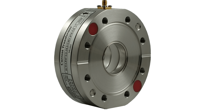
In-flange ICT
- In-flange ICT are mounted directly in the beam line.
- Available for many pipe diameters from 1” to 250mm.
- Also with elliptical aperture or other arbitrary shape aperture. Ceramic gap, shields and wall current bypass are included.
- Bellows are not required.
- Material AISI-304, 316LN on option
- Bakeable up to 185°C
- UHV compatible


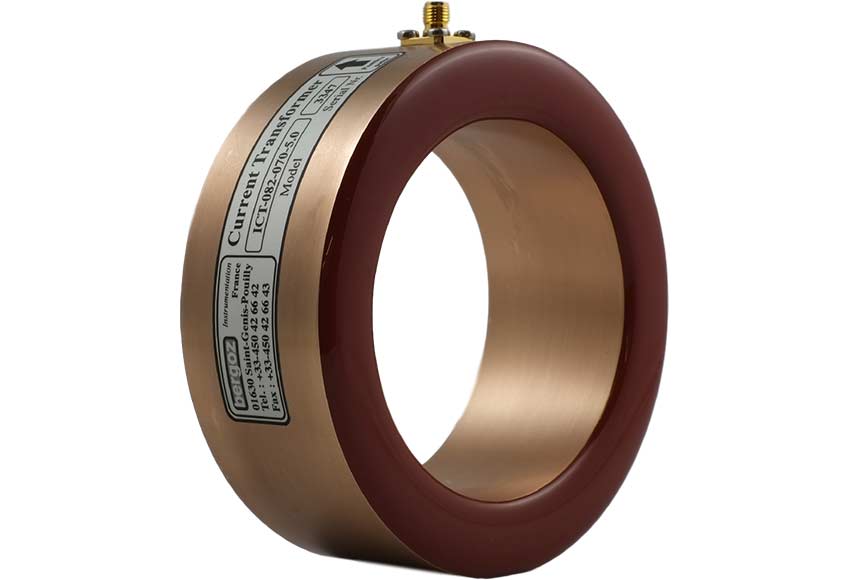
In-air ICT
In-air ICT installation, over the vacuum chamber requires installation of a “gap” to prevent the wall current from flowing through the ICT aperture.
The gap can be a brazed ceramic ring or an organic material O-ring depending on the vacuum requirements.
Typical installations include bellows, a wall current bypass and an electromagnetic shield enclosing the ICT completely.
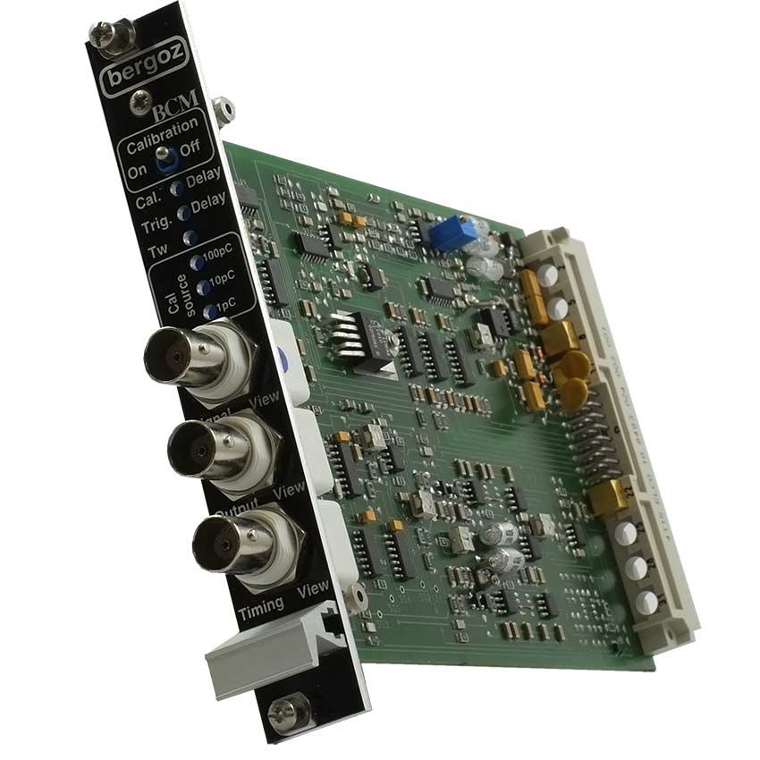
BCM-IHR-E
BCM-IHR-E processes the signal from an ICT.
Specially developed hybrid circuits amplify the charge and integrate it with low noise and high linearity.
Output is a bipolar voltage directly proportional to the beam charge.
A built-in Calibration Generator provides on-line assurance of measurement reliability.
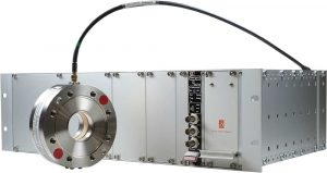
BCM-IHR-E inserts into a wired station of BCM-RFC, the 19” 3U RF-shielded chassis including power supplies.
Up to 10 stations per chassis can be installed.

Environment
Temperature
- In-air models: 100°C (212°F) any time
- In-flange models: 100°C (212°F) any time, 150°C (300°F) on option, 185°C (365°F) on option
Core saturation
- 2 mT radial field
- 2A permanent DC current
Radiation damage
- Standard SMA PTFE: 1E3 Gray max
- Rad-tolerant SMA PEEK: 6E7 Gray max
- 1E17 n/cm2 max

